ITALPRESSE FIRE CORE DOOR LINE
PROJECT SPECIFICATIONS
The plant is designed to produce compression moulded VERMICULITE PANELS according
to the following production parameters:
LOW DENSITY HIGH DENSITY
– Raw panel dimensions mm 870 x 2,050 mm min 1,200 x 2,500
max 1,200 x 2,200
– Finished panel size mm 850.9 x 2,032 min 2,133.6
max 2,438
– Average panel size mm 1,200 x 2,200
– Initial vermiculite
density
(to be verified) Kg/m3 200 to 281
– Final vermiculite
density Kg/m3 490 to 505 1,100 to1,140
– Initial min. thickness mm 73,2 225,5
– Final thickness mm 41±0,1 41±0,1
– Max specific pressures
on raw panel sizes Kg/cm2 15 50
(PSI) (213) (710)
– Anticipated specific
pressures on raw panel
sizes Kg/cm2 12 45
(PSI) (170) (640)
– Max temperature 200°C (392 °F)
– Working temperature 130°C (266 °F)
– Production capacities panels/yr. 240,000 at 86% of max capacity
panels/yr. 278,800 at 100% of max capacity
– Normal production
cycle time 1,110 seconds = 18.5 minutes
– Min cycle time 960 seconds = 16 minutes
– No. weeks per year…………………….48
– No. days per week………………………5
– No. hours per day……………………..24
– Efficiency………………………….…..80%
PRESS PLANT DESCRIPTION
(DRAW NO. 7388/D)
LINE TO FILL THE FEMALE MOULDS
This part of the line includes all the stations required to load vermiculite into the moulds.
Mechanical and electronic detectors will verify the presence of the raw material in the mould
and if the top cover has been positioned correctly.
POS.1.1 LOADING STATION
Where the vermiculite mixture is loaded into the mould.
– table dimensions ca. mm. 1400×3000
– motorized driven rollers – lengthwise movement of the mould
– motorized chains – crosswise movement of the mould
– motors controlled by inverters
– fixed and movable stops for proper positioning of the mould
– special detector to verify that the vermiculite mixture has been loaded
POS.1.2 TRANSFER CHAIN CONVEYOR
– table dimensions mm. 2800×1800
– motorized chains controlled by inverter
POS.1.3 SHAKING STATION
In this position, the mould is shaken to level the vermiculite for uniform density.
– table dimensions mm. 2800×1800
– motorized chains controlled by inverter
POS.1.4 TRANSFER CHAIN CONVEYOR
– table dimensions mm. 2800×1800
– motorized chains controlled by inverter
POS.1.5 TOP STEEL COVER LAY DOWN STATION
In this position the top steel plate will be laid down
into the mould. The tolerance between the top-cover and mould
parts will be very tight.
– table dimensions mm. 2800×1400
– motorized chains controlled by inverter
– tilting adjustable stop
– fixed stop and side pushing bar
– special sensors to verify that the top steel plate is correctly
positioned in the mould
POS.1.6 NO. 3 TRANSFER CHAIN CONVEYORS
– table dimensions mm. 2800×1800
– motorized chains controlled by inverter
– the conveyors will be in 3 independent sections and be utilized
as buffer stations
POS.1.7 ADJUSTABLE TRANSFER CONVEYOR
This device will provide to reduce the dead time during
the loading phase.
– table dimensions mm. 2800×1500
– motorized chain transmission crosswide
– gear box controlled by inverter
– this motorized table is on a scissor lift
POS.1.8 VERTICAL LIFT STATION AND PUSHER FOR THE MOULDS
This station receives the moulds loaded with the Vermiculite.
The moulds are aligned, centered, and lifted in order to push the
moulds one by one into the multi-daylight loading device (Pos. 2.1)
– tabel size mm. 1450×2800
– lift capacity Kg. 5000
– motorized crosswise chains controlled by inverter
– free lengthwise rollers conveyor mm. 1400×2800
A special push-bar installed on the scissors lift loads the moulds
into the multi-daylight loading unit (pos. 2.1).
– pusher stroke mm. 2800
– push thrust Kg. 1500
HYDRAULIC HOT PRESS LINES
The moulds will be transferred into the presses and pressed under pressure and heat to
produce the panels of the required density.
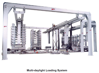
POS.2.1 MULTIDAYLIGHTS LOADING UNIT
This device has eight free rollers daylights, each one
will carry a mould at the same level of the press platens.
This unit automatically moves left & right in order to
serve all the three presses.
– platen dimensions mm. 1420×2600
– daylights no. 8
– daylight opening mm. 220
– loading side mm. 1400
Special adjustable vertical rollers to guide the moulds as they are loaded
Left & right automatic movement by reduction gear motor
POS.2.2 NO. 2 VERTICAL LOADING PUSHERS FOR LOW DENSITY PANEL
In front of the press (pos. 2.3) there are two special
frames each one carrying a vertical bar to push the moulds
from pos. 2.1 into the multi-daylight presses (pos. 2.3).
– units no. 2
– pusher stroke ca. mm. 3000
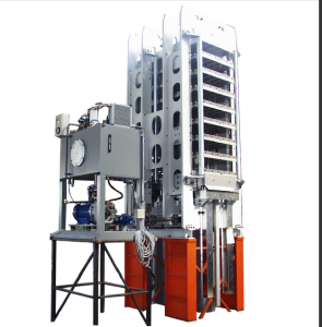
POS.2.3 NO. 2 MULTIDAYLIGHT PRESSES MOD. “IBN 9/17”
– platen dimensions mm. 970×2140 (38”x84”,25)
– daylights no. 8
– intermediate platens no. 7
– loading side mm. 970
– daylight opening mm. 220
– cylinders stroke mm. 1760
– working temperature max 200° C (392°F)
average 130° C (266°F)
– heating by thermal oil
– special vertical free rollers to guide the moulds entering the press
– max specific pressure on panel mm. 870×2050 (34.25” x 80.70”)
Kg./cm2 17,5 (249 PSI)
– total thrust metric ton. 312
– thrust cylinders no. 6
– diameter of each thrust cylinder mm. 150
– installed power kw. 21
– upstroking speed mm./sec. 85
– downstroking speed mm./sec. 100
– time to reach max pressure sec. 5
– press weight ca. Kg. 32.000
– FRAMES: Weld free steel plate ring frames
CNC machined
– PLATENS: solid steel plate – drilled for
circulation of thermal fluid
POS.2.4 NO. 2 VERTICAL UNLOADING EXTRACTORS FOR LOW DENSITY PANELS
Removes the pressed moulds from the presses and transfers them into the
multi-daylight unloading unit (pos. 2.8)
– max horizontal stroke ca. mm. 3000
– units no. 2
POS.2.5 VERTICAL LOADING PUSHER FOR HIGH DENSITY PANEL
In front of the press (pos. 2.6) there is a
framework carrying a vertical bar to push the moulds
from pos. 2.1 into the multi-daylight press (pos. 2.6).
– pusher stroke ca. mm. 2800
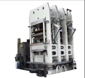
POS.2.6 TWO DAYLIGHTS PRESS MOD. “IBN/3-50”
– platens dimensions mm. 1420×2590 (56”x102”)
– daylights no. 2
– intermediate platen no. 1
– loading side mm. 1420
– daylight opening mm. 475
– total cylinders stroke mm. 950
– max platens temperature ° C 200 (392°F)
– working temperature ° C 130 (266°F)
– heating fluid: thermal oil
– special vertical free rollers to guide
the moulds as they enter into the press
– max specific pressure on panel
1200×2500 Kg./cmq 50 (711 PSI)
– total thrust metric ton. 1500
– thrust cylinders no. 6
– diameter of each thrust cylinders mm. 320
– installed power Kw. 48
– upstroking speed mm./sec. 106
– downstroking speed mm./sec. 100
– time to reach max pressure sec. 9
– FRAMES: Weld free steel plate ring frames
CNC machined
– PLATENS: solid steel plate – drilled for
circulation of thermal fluid
– CYLINDERS: Forged steel
POS.2.7 VERTICAL UNLOADING EXTRACTOR FOR HIGH DENSITY PANELS
Removes the pressed moulds from the press in (pos.2.6) and transfers them into the
multi-daylight unloading unit (pos. 2.8)
– max stroke ca. mm. 2800
POS.2.8 MULTI-DAYLIGHT UNLOADING UNIT
Receives the pressed mould / panels from the presses.
– platens dimensions mm. 1420×2600
– daylights no. 8
– daylight opening mm. 220
– unloading side mm. 1400
– special vertical free rollers to
guide the moulds during their movement
– left & right automatic movements
\
POS.2.9 UNLOADING LIFT STATION & EXTRACTOR
Vertical lift station that receives the pressed moulds one by one from the multi-daylight
unloading unit (pos.2.8)
– platens size mm. 1450×2800
– lift capacity Kg. 5000
– free lengthwise rollers
– motorized chains crosswise
– special device to extract the pressed moulds from the multi-daylight unloading unit
– stroke ca. mm. 2800
– pull capacity Kg. 1500
POS.2.10 ADJUSTABLE HEIGHT TRANSFER CONVEYOR
Reduces the dead time during the unloading phase.
The conveyor is on a scissor lift and moves to the required
working height to receive and transfer the moulds / panels.
– table dimensions ca. mm. 1500×2800
– motorized rollers
– motorized chain transfer
– motorized conveyor installed on a scissors lift table
PANEL STRIPPING AND STACKING LINE
In this section of the line, the panels are stripped from the moulds and automatically stacked
with 3 crosswise spacer strips automatically inserted between panels.
POS.3.1 TRANSFER CONVEYOR
– motorized roller conveyor mm. 1400×4000
– reduction gear motor controlled by inverter
POS.3.2 SPECIAL MOULD HOLDING STATION
When the mould arrives in this station, it is
clamped down in a fixed position. Special up-stroking pins
lift up the pressed panels in the mould together with the
steel top cover.
– table dimensions ca. mm. 1400×3000
– motor controlled by inverter
– adjustable clamping units to hold the mould down
– special pins to push up the pressed parts
POS.3.3 VACUUM UNLOADING UNIT
Two special handling units running on a common runway:
one provides to remove the top steel cover and lay it
down on a chain transfer (pos. 3.7).
The second unit provides to remove the pressed panel and
lay it down in stacks (pos. 3.4).
– max steel cover plate size mm. 1200×2500
– max steel cover plate weight kg. 350
– steel plate on left side stroke ca mm. 1500
– max lifting capacity Kg. 500
– special device to separate the top
steel cover from the vermiculite panel
– max vermiculite panel size mm. 1220×2550
– max panel weight Kg. 200
– three independent unloading stations (no. 2 for low
density and no. 1 for high density)
– max panel stack –12 panels with 30 x 30 mm spacers between each panel
– motors controlled by inverters
POS.3.4 NO. 3 MOTORIZED ROLLER CONVEYORS
Installed at floor level to receive the pressed board.
– dimensions mm. 1400×2800
POS.3.5 NO. 3 MOTORIZED ROLLER CONVEYOR
To supply each pos. 3.4 with caul panels.
– dimensions mm. 1400×2500
– special frame to align and hold the caul panels
POS.3.6 NO. 2 WOOD STRIP SPACERS RACKS
Each rack carries three 30×30 mm. wood strip magazines. These three
spacers will be placed between two Vermiculite panels. The
lower support-plate of each rack is vertically movable so that the
pick up height is constant.
Racks are fitted with wheels to facilitate easy loading of wood strips
POS.3.7 CHAIN TOP-PLATE RECEIVING CONVEYOR
The steel top plate is laid down on this conveyor and for
transfers to the cooling chamber.
– dimensions mm. 2800×2000
– driven chains controlled by inverter
POS.3.8 TOP STEEL COVER PLATES – COOLING CHAMBER
The steel top covers are collected by motorized chain
conveyor and tilted up 90° on edge so that turbulent air will
cool the panels effectively. It is designed to allow 15
tops to be in the cooling chamber with an output of one every 50 seconds
– air volume mc./hr. 20.000 (712.000 cft/hr)
– dissipated energy Kw./hr. 150 (500.000 BTU)
– inlet air temperature 25° (°F 77)
– outlet air temperature 45° (°F 113)
– transfer speed synchronized with female mould speed
– max top cover plates temperature 180°C (356 °F)
– outlet top cover plates temperature 100°C (212 °F)
– top plates in circulation no. 15
THE CHAMBER AND FAN-UNITS ARE NOT INCLUDED IN THIS OFFER
POS.3.9 TOP STEEL PLATE UNLOADING CHAIN CONVEYOR
The cooled (100°C) top cover plates are laid down on this
chain transport and moved to the transfer conveyor (pos. 3.10).
– dimensions mm. 2800×2000
– driven chains controlled by inverter
POS.3.10 TRANSFER CONVEYOR
Receives the top plate and transfers them back to the loading station
– dimensions mm. 1400×2800
– motor control by inverter
RETURN LINE FOR TOP COVER PLATES
The cooled top cover plates move back to the pick up station at the front of the line. During
this movement, the plates are inspected, cleaned, and release agent will be sprayed on. The
top cover plate may be removed from the line and replaced with a new one if needed (this
operation to be carried out during the maintenance period).
POS.4.1 TRANSFER CONVEYOR
– motorized roller conveyor mm. 1400×3000
– reduction gear motor controlled by inverter
POS.4.2 NO. 2 MOTORIZED ROLLERS CONVEYOR
– conveyor dimensions mm. 1400×3500
– motorized rollers driven by inverter
POS.4.3 BRUSHING MACHINE
To clean the top & bottom of the top cover plates.
– working width mm. 1400
– adjustable speed mt./1” 5-40
POS.4.4 MOTORIZED AND CENTERING ROLLERS CONVEYOR
This conveyor receives the top cover plates and
aligns and centers them within a tight tolerance.
– dimensions mm. 1400×4000
– tilting lengthwise stop
– twin horizontal pusher for centering the plate
POS.4.5 VACUUM UNIT
Picks up the top cover plate and lays it down on the mould
– max plate size mm. 1250×2550
– max lift capacity Kg. 400
– vertical stroke mm. 300
– transversal stroke mm. 2800
COOLING LINE FOR FEMALE TRAY
In this section of the line, the female moulds will be cooled, cleaned, inspected and returned
to the starting point.
POS.5.1 COOLING ZONE
The female mould is cooled down to 100°C (252°F) as required by the vermiculite
process.
A chain conveyor system delivers one female mould per minute through the system
This system works using forced air as cooling medium.
– air volume mc./hr. 40.000 (1.425.000 cft/hr.)
– mould weight Kg. 450
– max mould temperature at the
entrance °C 180 (°F 356)
– mould temperature at the
exit °C 100 (°F 212)
– total energy to be dissipated Kw./hr 284 (950.000 BTU)
– air volume mc/hour 40.000
– air inlet temperature ° C 25 (°F 77)
– air outlet temperature ° C 45 (°F 113)
– mould panels circulating no. 15
NOTE: THE COOLING CHAMBER AND FAN UNITS ARE NOT INCLUDED IN
THIS OFFER
POS.5.2 NO. 6 TRANSFER CHAIN CONVEYORS
– dimensions ca. mm. 1400×3000
– motorized chains controlled by inverter
POS.5.3 STATION TO REMOVE THE MOULDS FROM THE LINE
A gantry running on a single runway with both
magnetic and mechanical lifting units to lift and remove either top covers
or female moulds from the line. The movement is manually driven by the
operator.
POS.5.4 NO. 4 GRAVITY ROLLER CONVEYORS
– dimensions mm. 1400×3000
POS. 6 CONTROL ELECTRICAL PANELS
Master electrical control cabinets housing all the necessary programmable logic controls,
motor starters and overload protection devices. A single control console is provided with
operator interfaces to monitor the functions of all components of the line, set working
parameters, and provide both manual and automatic control the entire line.
PRICE SUMMARY
Project engineering and equipment design……………………………………………..EURO 350,000
All equipment as described in this proposal………………………………………….EURO 4,685,750
Ex-works, Italpresse, S.p.A. – Bagnatica, (BG) ITALY
Total cost of the engineering and equipment………………………………………..EURO 5,035,750
Cost of the engineering and equipment in US Dollars based on the current
exchange rate of EURO 1.00 = USD $1.35…………………………………………..USD $6,798,260
Estimated US import duties and clearance fees ……………………………………….USD $201,230
Paid at cost upon occurrence
Estimated cost of door to door freight from Italy to Virginia ………………………..USD $279,000
Paid at cost upon occurrence
On-site installation and equipment start-up costs ……………………………………..USD $230,000
Includes labour and travel expenses
Estimated total project cost……………………………………………………………..USD $7,508,490
ITALPRESSE TERMS AND CONDITIONS:
Prices: Quoted prices are in EURO Dollars.
Sales Tax: The quoted price does not include Virginia state and local sales or use
tax. It is the buyer’s responsibility to report and pay to the appropriate
taxing authority any sales or use tax that maybe due on this purchase.
Packing: Uncrated – Plastic wrapped – Loaded into estimated (34) 40’ O.T. Ocean
Containers
Delivery: Ex-works, Italpresse, S.p.A., Bagnatica, (BG) Italy
Delivery time: Ready for shipment approximately 9 months from receipt of signed order
and deposit, subject to factory confirmation at time of order.
Freight and Duty: It is the buyer’s responsibility to arrange and pay directly the US import
duties and door-to-door freight costs on occurrence.
Unloading: Unloading the machines from the containers on-site is the buyer’s
responsibility and expense. Italpresse will furnish a qualified person to
supervise the unloading process and advise on the placement of the
various components of the line.
Payment: 10% deposit with order
20% second payment due 60 days from order confirmation date
65% third payment due prior to shipment from the factory
5% final payment due upon completion of installation, but no later than
60 days from date of delivery to site
Warranty: Italpresse warrants their products against tested defects in materials and
workmanship for a period of 12 months. Normal wear items are not
covered by the warranty. The warranty includes parts and labor, but
does not include travel expenses for trouble-shooting and installation of
replacement parts. Seller disclaims all other warranties whatsoever,
expressed or implied, including all warranties of merchantability and
fitness for a particular purpose.
Offer Validity: 60 days from quote date.
Installation: Assembly on site and start-up by qualified ITALPRESSE technicians
mandatory at an additional charge of $230,000 USD, which includes
labor costs and travel expenses.
THE FOLLOWING ARE SPECIFICALLY EXCLUDED FROM THE SCOPE OF THIS OFFER
– Male & female moulds
– The cooling rooms for the male & female moulds including fans, pipes
– Thermal oil heating unit & platen temperature control system
– Walks ways, raised catwalks, guard railings for access around and across the plant
– Compressed air, filters and controls
– Dust and ventilation hoods and their extraction systems
– Support structures, grating, and protection rails for all the pits
– Pits and all concrete foundation preparation. ITALPRESSE ENGINEERING SPA will
supply detailed drawings and instructions
– Electric cables and their installation from your power distribution panels to our
main power terminal boxes
– Crane and fork truck rental to assist in on-site assembly of the machines
– Unloading of the machines from the containers on-site and moving them into place
for assembly